While electrochemical sensors detect oxygen reduction at the electrode surface, the optical method is based on energy transfer between an stimulated luminophore and oxygen.
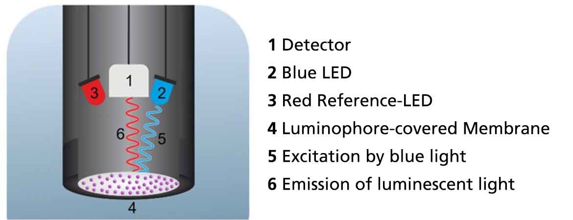
The main components of an optical sensor are two LED lights inside the sensor and a membrane covered with luminophores at the sensor tip. A luminophore is a substance that emits light after it has been previously stimulated with a light of shorter wavelength. The luminophores embedded in the sensor tip are illuminated with the blue light of an LED. The luminophore absorbs this energy and releases some of it in the form of red luminescence. A detector in the centre of the sensor detects the emitted red light of the luminophores and measures its intensity and lifetime. The intensity and lifetime of the luminescence depends on the concentration of dissolved oxygen in a sample. To evaluate the influence of oxygen on the resulting luminescence, the red light of a reference LED that is not influenced by oxygen is used for comparison.
If oxygen is present in a sample, the luminophores transfer part of the absorbed energy to the oxygen molecules after excitation. This process is also known as quenching. Quenching causes the luminophores to release less energy via light emission and thus reduces the intensity and lifetime of the luminescence in the presence of oxygen.
Evaluation of the luminescence lifetime
The Lovibond® optical sensor uses the lifetime-based luminescence method to determine the dissolved oxygen concentration. This method has the advantage over intensity-based luminescence that the optical sensor is more stable in the long term and calibration is seldom necessary.
The reason for this is that natural ageing processes of the luminophores have no influence on the lifetime of the luminescence, but they do on the intensity.
A red reference LED is used to analyse the lifetime of the luminescence. The light of the reference LED is pulsed with a constant frequency. The emitted light of the luminophores has the same pulsing, but with a time delay compared to the reference light. This time delay between the pulses is called phase shift (phi). The phase shift depends on the oxygen content in the sample. In the absence of oxygen, the phase shift reaches its maximum (Figure 2 A). As the concentration of dissolved oxygen increases, the phase shift decreases continuously (Figure 2 B).
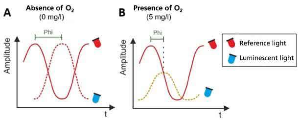
Figure 2: Measurement of the phase shift in the absence (A) and presence of dissolved oxygen (B).
The change in phase shift at different concentrations is non-linear and can be calculated using the so-called Stern-Volmer equation as soon as two measuring points are known. The results can be displayed by of a calibration curve. The corresponding calibration data are stored on the SD card supplied and each data set is precisely assigned to the respective sensor via a serial number.